FlareonzVerse
I'm written in c++
Dev Journey: Procedural skyboxes in GLSL
Flareonz44 - June 08 2024
Introduction
For the past two months (maybe even longer), I have been implementing the sky system in my game “Beyonder: Mars Research,” and I discovered that there are many ways to achieve this.
The main and most important method is through the use of skyboxes. Generally, these consist of a 3D cubic model and a texture of a landscape. However, as I was testing how it looked, I realized that this was not what I was looking for; I needed a different kind of skybox other than the one traditionally used. It was then, while reading other posts (which I will include below), that I found the perfect solution: procedural skyboxes.
But before going into detail about this, it’s better to start from the beginning, understand how the basic model works, and then see how this can be achieved procedurally using shaders.
How it works
A skybox is essentially a way to simulate spaces beyond the playable map in a game, giving the player a sense of immersion within the world. This simple technique has been used since the early generations of consoles and continues to be employed today.
The trick involves creating a cube with a 360-degree landscape texture that will be drawn in the background (you may disable depth test at this point and then reenable it). This cube must always be perfectly aligned with the center of the main camera because any offset will break the effect. If the projection of the objects in our cubemap is accurate, it creates the visual illusion that the objects represented in the texture are far away.
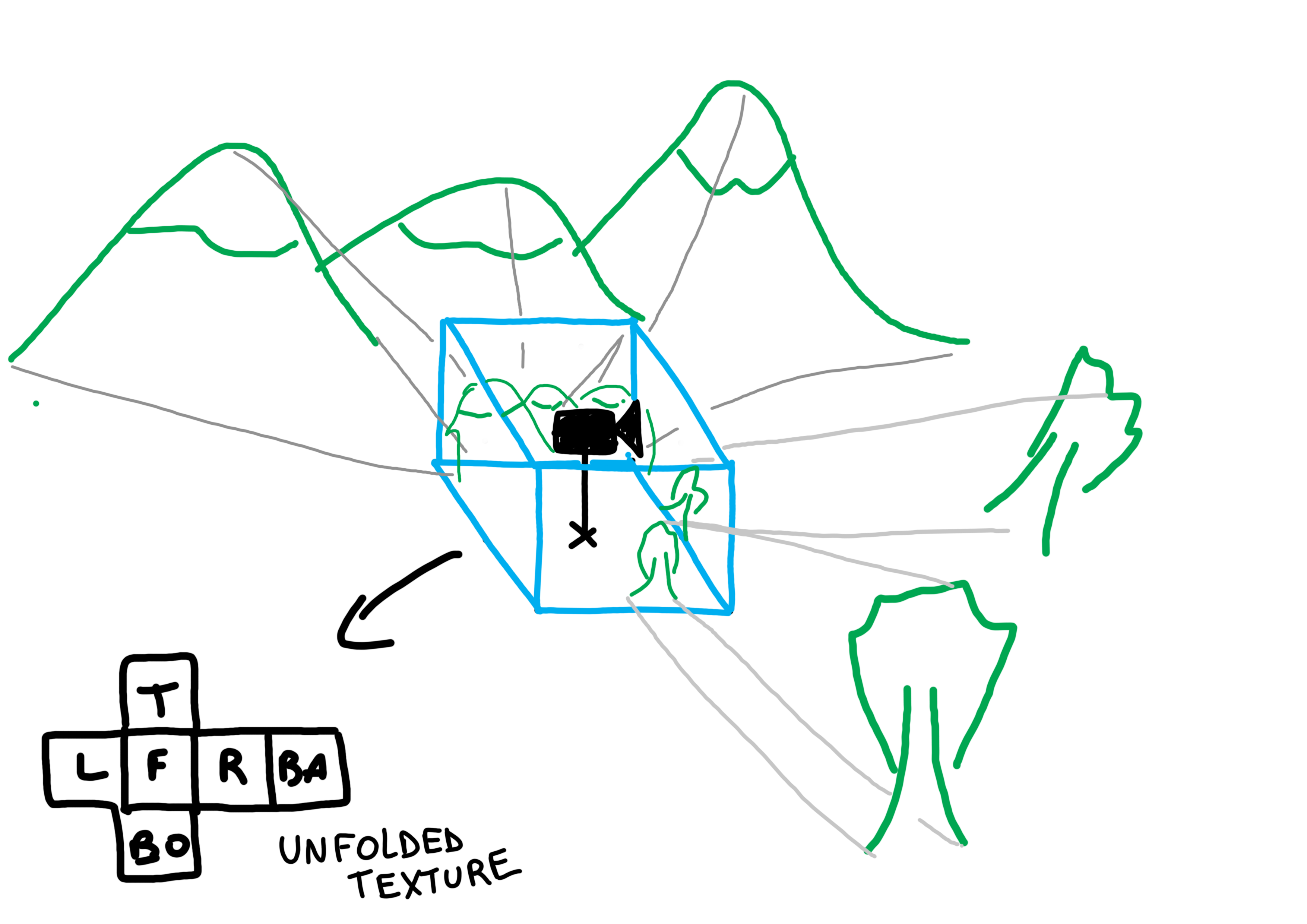
In the following diagram (handmade and simple, don’t expect accuracy :P), you can see how the projection of objects (mountains, trees, etc.) is printed onto the cubemap to generate the final texture. When we unfold this final texture, we can see how each side of the cube corresponds to the directions: front, left, right, back, top, and bottom.
Limitations
However, although it is a very good and popular technique, it has its limitations.
First of all, it requires a texture, which means that if we want to project a sky with a certain color, clouds, or other elements, we have to create that texture ourselves. This involves going through the entire process of scene editing, effects, and rendering. The problem arises when we realize that it is not a normal rendering, but a special projection, as we must create a cubic projection of our scene in a texture and then export that texture for use.
Additionally, the texture must be of high quality; otherwise, pixelation could break the immersion effect. It sounds complex, and indeed, it is.
But the main reason I decided to discard this method for creating skyboxes is that I need something more dynamic. For my game, I plan to implement a day and night system, and rendering a static texture would be useless at the end of the day.
Procedural Skyboxes
Now, this is where it gets interesting — and complex.
We already know that we can’t create skyboxes using textures, so we are left with only one option: generate them in real time. The best way to achieve this is undoubtedly by using shaders.
In a nutshell, a shader is a small program that runs on the computer’s video card instead of the main processor.
All computers have a graphics processor, either integrated into the main processor or in a dedicated video card; otherwise, we would not be able to see anything on the screen.
I remember when I was learning to program, I read in a StackOverflow forum that there was nothing more difficult than programming shaders.
But the reality is that it is not as complex as it seems, although it does require a lot of abstraction, since the execution pipeline is very different from a traditional program, so many things might not work in the same way.
One of the things to keep in mind when programming shaders is that we are limited by processing capacity, so we cannot make programs that are too complex or have too many iterations, as this could significantly affect performance.
Of course, an Nvidia 4090 will run almost anything, but a guy with integrated graphics on their laptop with a Celeron processor will notice a negative impact on frame rate, resulting in a poor gaming experience.
Now, before we can think of a solution for our procedural skybox, we must understand one last thing about shaders: their pipeline.
The way these programs actually run is very complex, so I will just give a simple overview: After generating the necessary vertices for each model on screen, the first stage of the shaders is executed: the Vertex Shader, which has the ability to shape the vertices. After the models are processed, the second part is executed: the Fragment Shader, which is in charge of texturing and coloring. It is precisely at this point where we are going to focus to create our skybox.
Setup
Before we can start designing a nice skybox for our game, we need to create a reference system that will allow us to draw correctly. After trying several ideas (and researching and reading other developers’ work), the approach that turned out to be the most effective and easy to use is to create a coordinate system similar to latitude and longitude, but using values that go from 0 to 1 and can be represented through a Vec2 data type.
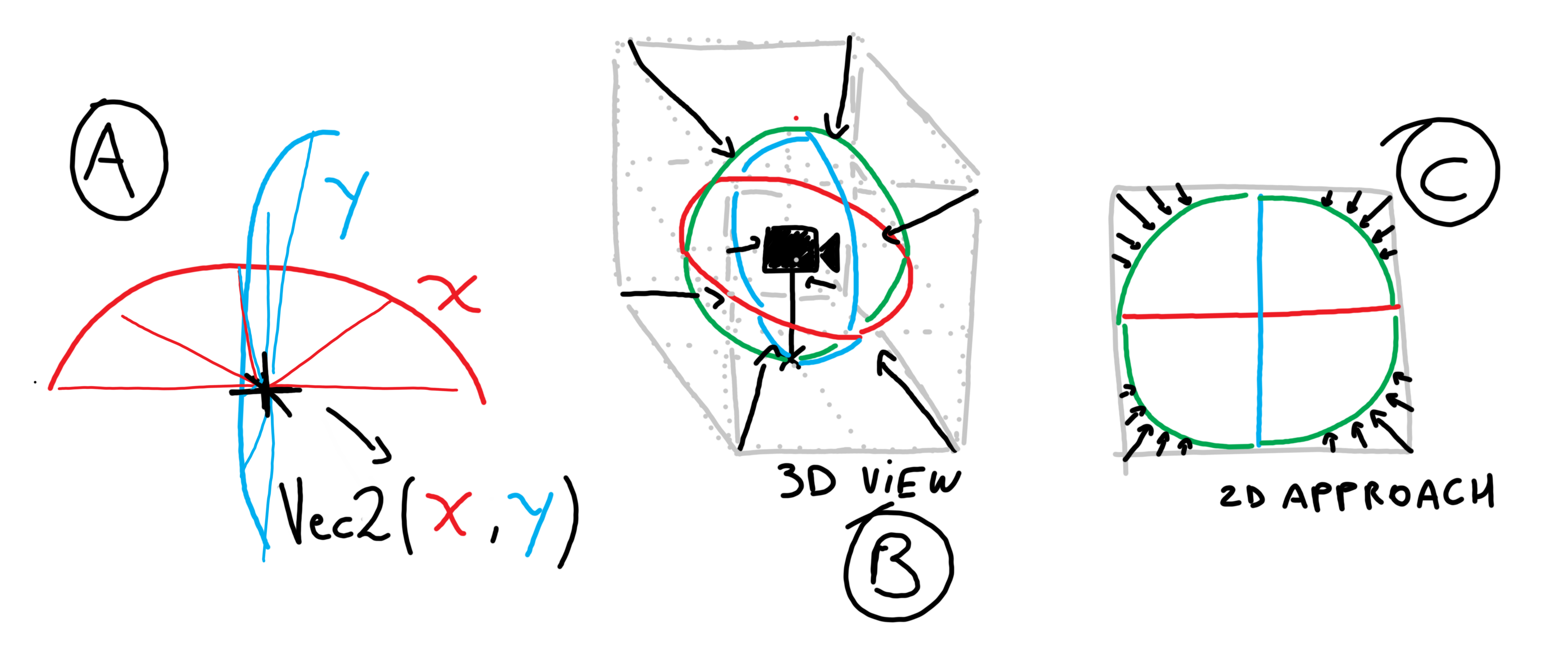
In Image (A), you can see my idea of having an X and Y component of a two-dimensional vector, representing rotations around a virtual sphere centered on the camera.
This virtual sphere is crucial because it allows us to achieve something that a cube cannot: the equidistance of points. This enables us to make better calculations by maintaining uniform distances from different points on the sphere to the main camera’s point of view. Additionally, it allows us to apply functions as we would on Cartesian planes.
However, creating this virtual sphere involves transforming the positioning system of each pixel on the cube (remember that we are still working with the 3D cube, but the texture will not be a PNG; instead, it will be generated by a shader). Essentially, we need to get the positions of each point on the cube and convert them to their corresponding positions on the virtual sphere.
In Image (B), I drew a 3D diagram of what we want to happen: the surface of the cube transforms to fit the sphere perfectly by stretching and contracting.
In Image (C), there is an approximation of the same idea, but in a 2D case, where the edges of a square’s textures transform to those of a circle.
A funny thing about this is that many posts on the internet show how to achieve all this by simply using Unity’s node graphs, which makes the task much easier since it abstracts away all the mathematical calculations.
But I don’t use Unity, so I had no choice but to reverse engineer the node logic and apply the correct calculations to achieve similar results.
Well, now that we know what we want, we just need to apply all this in the shader. For this, we need our vertex shader to pass a particular variable to the fragment shader. This variable will be the position of each pixel in the world space coordinate system. We achieve this simply by adding this line to the vertex shader:
fragPos = vec3(matModel*vec4(vertexPosition, 1.0));
This line returns the position of each fragment in a vec3 by multiplying the matrix that represents the spatial transformations of the 3D model by the position of the current vertex. This will help us perform trigonometric calculations later.
Then, in our fragment shader, we will use these two variables to work on the skybox.
void main(){
    vec3 rp = normalize(cameraPos-fragPos); //relative position
    vec2 uv = vec2(atan(rp.z, rp.x)/dPI, (asin(rp.y)+hPI)/PI);
    //...
}
First of all, we are calculating the relative positions of each vertex to the camera. The camera position is given to us by our main program — in my case, I am using Raylib — and I simply pass the camera positional values to the shader. It is important to note that this vector is normalized, meaning its components are in a range from 0 to 1.
The next line is the most complex, as this is where we build our positioning vector.
The first component is given by the inverse tangent of the x and z components of our relative position. This essentially gives us the rotation of the vector, and its subsequent division by dPI (double of PI) normalizes it to an ideal range for our calculations.
The second component is given by the inverse sine of the height component of the vector, which must be adjusted using hPI (half PI) and PI.
Once we have these lines ready, we can finally start designing our skybox.
Designing the skybox
This part is a bit more fun, because once we have the functional base, we only need to start playing with mathematical functions, interpolations, and masks. If we manage to mix all this well, we can achieve some of the most beautiful landscapes to appreciate.
Let’s see how we can achieve some basic effects for our sky.
Drawing the Sun
To draw the silhouette of the sun, we only need the light direction vector. This parameter will depend on the implementation in your game; in my case, it is a variable passed to the shader. With this, we can precisely calculate the point on our virtual sphere where the sun will be. However, if we want to paint a circle of radius X, we must first create a function that returns the angle between two vectors in 3D:
float angV3(vec3 v1, vec3 v2) {
    return acos(dot(normalize(v1), normalize(v2)));
}
With this, we can implement a threshold that allows us to draw a perfect circle of radius less than or equal to the threshold.
As the shader is executed for each pixel of the model, all those points that, when compared with the angle of the sunlight direction, result in being less than or equal to a threshold X that we have configured will be painted in one color or another. The resulting code is as follows:
void main(){
    // ...
    float ang_sun = angV3(rp,sunLightDir);

    if (ang_sun < .2){
        finalColor = vec4(vec3(1), 1.0); // white
    }else{
        finalColor = vec4(vec3(0), 1.0); // black
    }

    // in Raylib, finalColor is the same as fragColor in other implementations
}
And the result is the following:
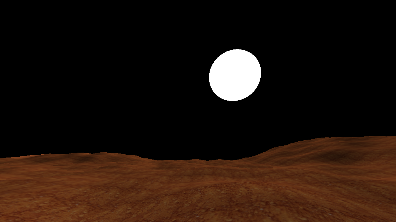
You can see that our shader draws a perfect circle, thanks to the spherical coordinate system we created earlier.
Another noteworthy fact is that with this same code, we can draw any type of celestial body, whether it’s a moon, an asteroid, etc. Simply by creating a direction vector and making it rotate throughout the day, we get a simple simulation of a planetary rotation system.
Light Strength Mask
Another fundamental aspect of a dynamic skybox is the implementation of a lighting system based on time. By having a reference for the passage of time — in my case, the sun, which makes a full rotation around the camera — you can determine when it should be light and when it should be dark. Based on that, you can decide if the color of the sky will be reddish or black (in my case, I am simulating the Martian surface, but for a terrestrial simulation, the colors would be light blue, white, and dark blue for the night).
To achieve this, we will use the relative position and direction of the sunlight.
First, we need to understand that to create a day and night system by mixing colors, we will use the mix(ColorA, ColorB, X); function. This function takes two colors and, given a value between 0 and 1, makes a linear mix between both colors, with 0 being color A and 1 being color B.
We want to obtain these values from 0 to 1 to mix the color of the day sky with the color of the night sky, for which we need to create a gradient mask between 0 and 1 that indicates when it is day and when it is night. We do this by mapping values from 0 to 1 based on the relative position vector, using our positioning variable system.
Knowing that our Y component of the UV vector goes from 1 to -1, we can simply use smoothstep(); to achieve a linear transition between the ranges we pass it, knowing that the rest will be limited, as if we were using clamp.
The idea is to use a range such that the upper hemisphere of our virtual sphere is black, the lower part is white, and there is a gradient transition along the equator line.
void main(){
    //...
    float light_mask = smoothstep(-.1, .1, rp.y);

    finalColor = vec4(vec3(light_mask), 1.0);
}
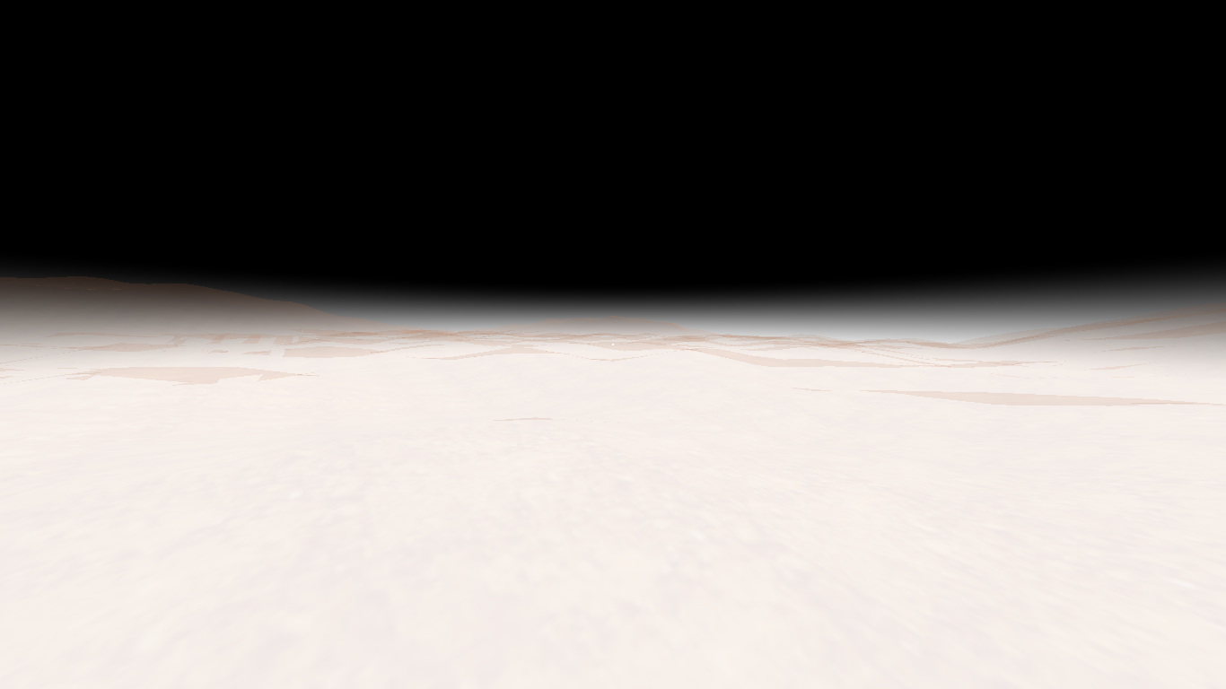
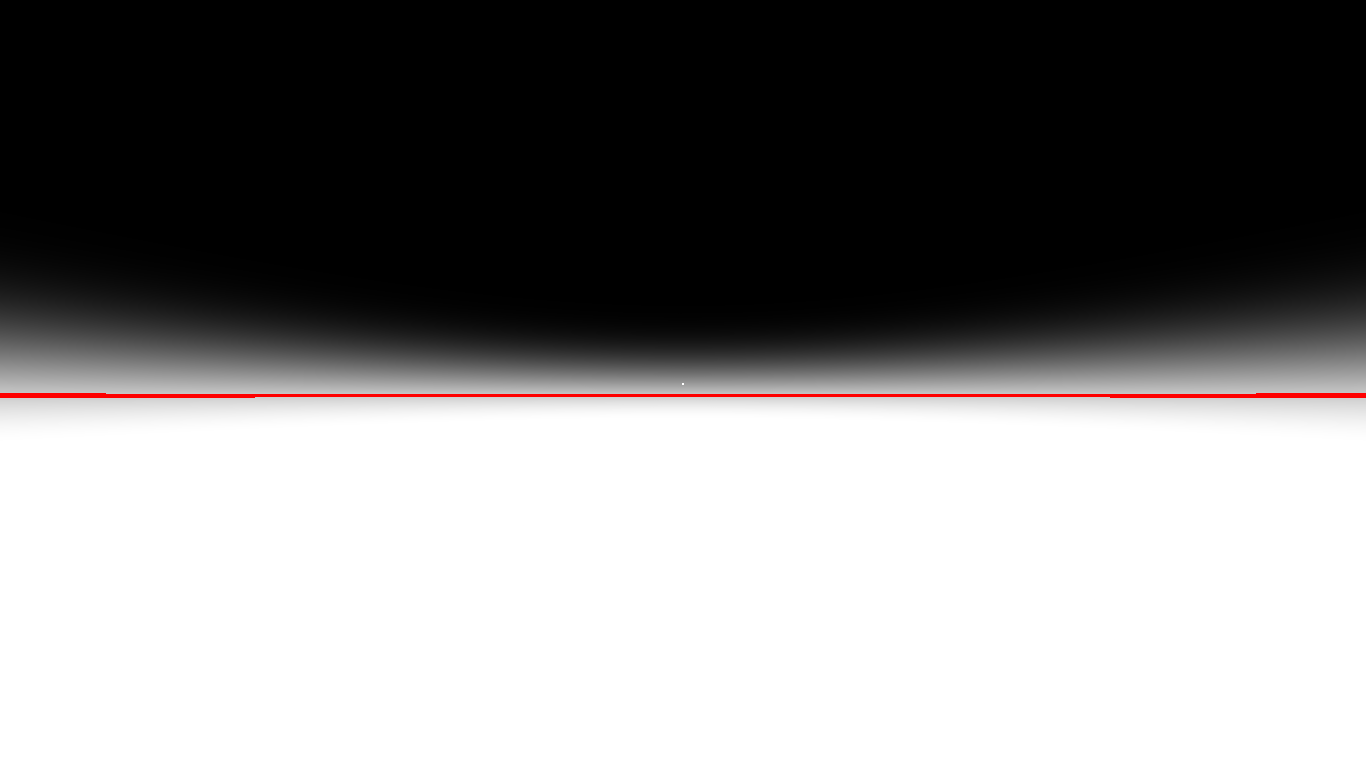
Rendered result (terrain is transparent to let you see below horizon):
With this, we can achieve approximately what you see on the left side of the diagram below. We see that if we take a sector of this dome, it has a gradient printed along Y. Use black for values of 0 and white for values of 1.
However, this mask is useful to simply know what colors it will take as the sun moves through the different values of our Y component.
If instead of using the relative position, we use the direction of the sunlight, we would obtain the complete dome painted with intensities according to the position of the light in Y. On the right side of the diagram, you can see how the dome would look when taking a point of the mask and using it to see the intensities.
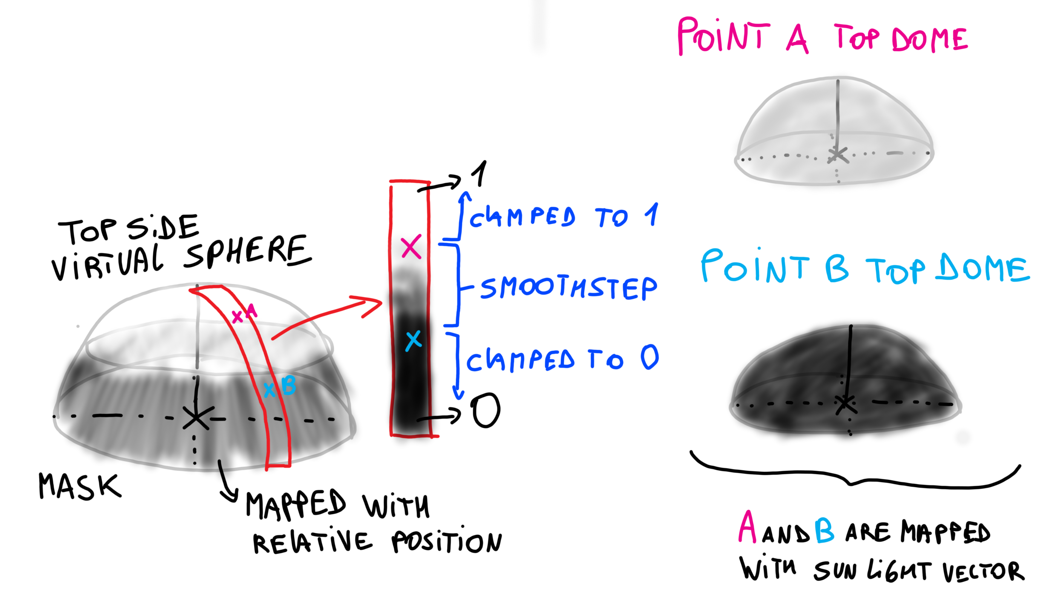 I messed up with colors, but you got the idea :)
But it should be noted that all this is really a visual support to help us see more graphically what values our float will take to mix colors. Until now, we established that the final color is given by our mix value, but now it is time to set the correct values to better appreciate this transition.
void main(){
    //...
    float light_mask = smoothstep(-.1, .1, sunLightDir.y);

    finalColor = mix(daycolor, nightcolor, light_mask);
}
And with this, we can finally have a transition between day and night!
The red line is equator line, just for reference.
Horizon Light Scattering
Now that we have a sun and a day-night system, the only thing left to talk about is sunsets.
Have you ever wondered why the sky is light blue during the day and red at sunset?
This is mainly due to a phenomenon known as light scattering. When sunlight interacts with the atmosphere, certain wavelengths of white light interact more than others and therefore tend to disperse more. This dispersion causes these particular waves to reach our eyes as they bounce in all directions.
At sunset, the same thing happens, but as the sun is over the horizon, the waves that previously bounced in all directions are now lost, and only the waves that didn’t bounce, which are closer to the red spectrum, follow their trajectory.
The reality is that this physical phenomenon is much more complex, and simulating it accurately on a computer is very challenging.
There are many papers that discuss this subject and how to realistically simulate light scattering, but for my game, I don’t need highly faithful simulations. Instead, I’ll use a simple gradient to simulate light scattering in a very basic way.
For this, we will again use a mask that acts as a blend of colors between the sky and the horizon. This blend will only become visible when it is getting dark, so we will use the light intensity mask to determine when it is dusk.
It’s quite simple in the sense that we will apply everything we did before to achieve this effect. The first step is to create the mask that we will use to blend with the color of the sky:
float horizon_mask = pow(smoothstep(.40, .52, uv.y), 3);
We cube the result, which allows us to have a slightly smoother gradient transition.
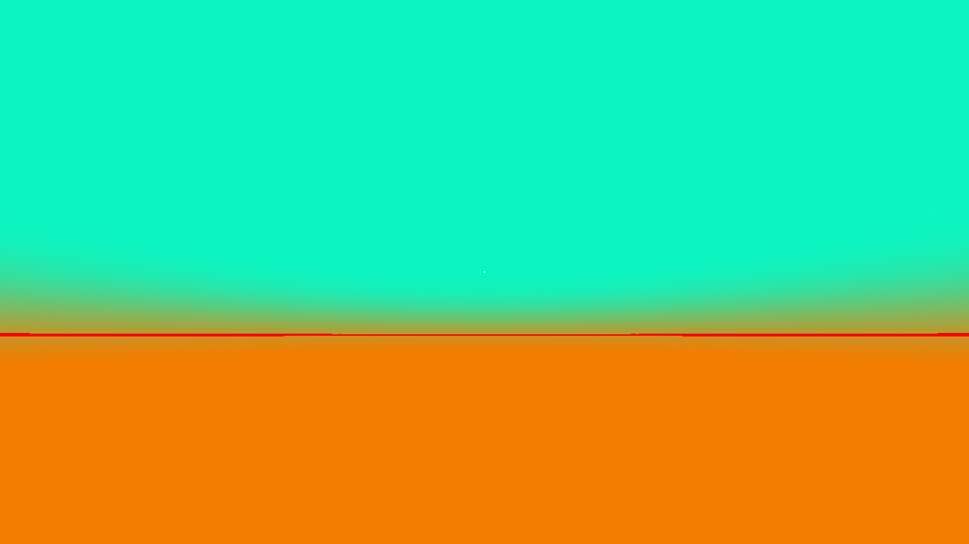
And now we will make a blend to see how it looks:
vec4 daycolor = vec4(0.043, 0.961, 0.761, 1.0);
vec4 horizoncolor = vec4(0.949, 0.49, 0, 1.0);
finalColor = mix(daycolor, horizoncolor, horizon_mask);
You can see that we got the blend we wanted:
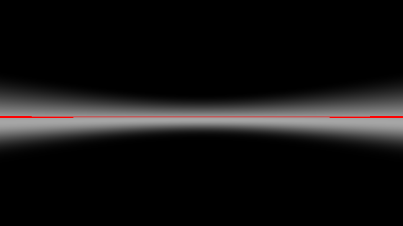
But now we have to configure it so that this blend only happens when it is getting dark. To do this, we need to create an activation mask for the horizon blend:
float horizon_activation = pow(smoothstep(.25, 0, sunLightDir.y), 3) * smoothstep(-.2, .15, sunLightDir.y);
This results in the following mask (I used the relative position for the screenshot):
Finally, we just need to make two mixes:
finalColor = mix(daycolor_, nightcolor, light_mask);
finalColor = mix(finalColor, horizoncolor, horizon_mask*horizon_activation);
In the first mix, we combine the day color with the night color based on the daylight mask. Then, we take that resulting color and mix it with the sunset color based on the horizon mask. The difference is that this blend is also affected by the horizon activation, which will only happen when the sun is setting and will disappear when the sun is low enough on the horizon.
Putting together everything we did before, we can achieve a relatively simple sunset.
yeah, maybe those colors sucks, but it’s just a demo
All that remains is to play with all the variables until the perfect combination is achieved!
Final Words
I must say that programming the procedural skies was not an easy task. It required not only many hours of trial and error, but also a lot of research and learning. I read many articles, pages, and watched videos to achieve the perfect implementation in my game.
Undoubtedly, much of what I detail here I did not find on the internet, so I decided to publish it for anyone else who wants to understand how to build this type of skybox using pure GLSL.
Below, I leave links to other blogs that I read and that gave me the key ideas to design the sky.
I know I still have to cover many other things that can be achieved, such as procedural clouds, stars, and many other phenomena that can be replicated in a skybox. I will probably cover some other effects in the future.
Until another dev journey!
Beyonder: Mars Research Sunset
Links
Firewatch Procedural Sky (their skybox is insane epic)
Reaching for the stars - Jannik (awesome post, check it out)